|
|

| IntelligentMagnetics™ Motion Control | ||||||||||||||||||||||||||||||||||||||||||||||||||||||||||||||
| Industrial/Aerospace/Military Specifications | ||||||||||||||||||||||||||||||||||||||||||||||||||||||||||||||
| Designs by the inventor of the Slotless Wide Airgap Motor | ||||||||||||||||||||||||||||||||||||||||||||||||||||||||||||||
Permanent
Magnet Motors |
||||||||||||||||||||||||||||||||||||||||||||||||||||||||||||||
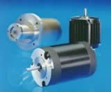 |
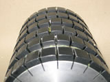
We offer EC Motors, both physical and Virtual Prototypes, which includes 3D printed slotless (Wide Airgap) BLDC motors, slotless permanent magnet BLDC motors, and traditional torque motors of the BLDC type with a complete range of electronic controls/drivers. Although, we now prefer to supply "apps" that embody Virtual Prototypes which allow modist tailoring of the design characteristcs for applications adjustments without expensive modification and retooling of physical machines. The Virtual Prototype represents a huge investment savings over machined physical devices. Jackson Research EC motors meet or exceed EU Commission Regulation (EC) No 640/2009 regarding ecodesign requirements. |
 |
||||||||||||||||||||||||||||||||||||||||||||||||||||||||||||
 |
 |
|||||||||||||||||||||||||||||||||||||||||||||||||||||||||||||
Transverse
Flux Machines |
||||||||||||||||||||||||||||||||||||||||||||||||||||||||||||||
 |
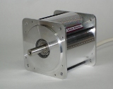
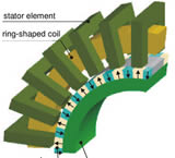
Transverse Flux motors and generators are the object of considerable alternate energy research. One of the newest incarnations is an inside out version which only achieves approximately 50% of its potential and suffers complete demagnetization. Jackson Research has developed and constructed machines that overcome those deficiencies achieving efficiencies over 90%. These inside out machines are proprietary. |
 |
||||||||||||||||||||||||||||||||||||||||||||||||||||||||||||
Embedded
Motion Controls |
||||||||||||||||||||||||||||||||||||||||||||||||||||||||||||||
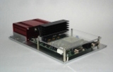 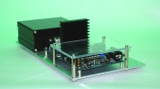 |
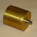
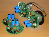
We use sensored drives exclusively to achieve continuous stall torque. And, it is the only means to achieve precision profiling. The computer on a chip and proprietary PID closed loop operation coupled with precision optical encoders or our proprietary resolver technology provides the ultimate in precision motion and positioning. |
  |
||||||||||||||||||||||||||||||||||||||||||||||||||||||||||||
Permanent
Magnet Solid State Encoders / Synchros / Resolvers |
||||||||||||||||||||||||||||||||||||||||||||||||||||||||||||||
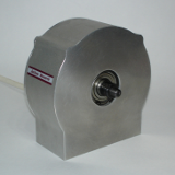
Jackson Research encoder technologies are interchangeable devices with choices of pole counts and shaft hole sizes. They can be furnished in several grades of precision. All units are designed for harsh environments. Specialized permanent magnets provide stable accurate reliable operation over the entire temperature range. Simple encoder winding alignment during assembly is achieved by rotation of the encoder housing with the encoder magnet fixed to the shaft. Features include:
These proprietary devices are fully solid state. No sine wave inputs are necessary. Demodulation is no longer required. All Synchro/Resolvers outputs are pure sine waves in real time. Any latency or phase delays are within the device resolution and are not measureable. |
||||||||||||||||||||||||||||||||||||||||||||||||||||||||||||||
Resolution |
||||||||||||||||||||||||||||||||||||||||||||||||||||||||||||||
| Resolution can never be better than the A/D converters used in the DSP MCU. | ||||||||||||||||||||||||||||||||||||||||||||||||||||||||||||||
|
||||||||||||||||||||||||||||||||||||||||||||||||||||||||||||||
PID |
||||||||||||||||||||||||||||||||||||||||||||||||||||||||||||||
|
||||||||||||||||||||||||||||||||||||||||||||||||||||||||||||||
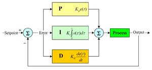
| The control system performance can be improved by combining the feedback (or closed-loop) control of a PID controller with feed-forward (or open-loop) control. Knowledge about the system (such as the desired acceleration and inertia) can be fed forward and combined with the PID output to improve the overall system performance. The feed-forward value alone can often provide the major portion of the controller output. The PID controller can be used primarily to respond to whatever difference or error remains between the setpoint (SP) and the actual value of the process variable (PV). Since the feed-forward output is not affected by the process feedback, it can never cause the control system to oscillate, thus improving the system response and stability. | ||||||||||||||||||||||||||||||||||||||||||||||||||||||||||||||
Motion
Profile |
||||||||||||||||||||||||||||||||||||||||||||||||||||||||||||||
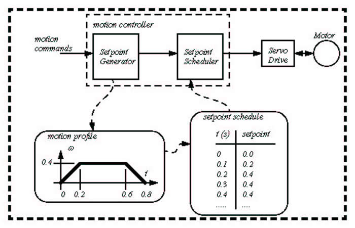
| The combination of a motion controller, drive and actuator is called an axis. When there is more than one drive and actuator the system is said to have multiple axes. Complex motion control systems such as computer controlled milling machines (CNC) and robots have 3 to 6 axes which must be moved in coordination. | ||||||||||||||||||||||||||||||||||||||||||||||||||||||||||||||
Moving a system from one steady position to another (point-to-point motion) following the fastest possible motion within an allowed maximum value for speed, acceleration, and jerk, will result in a third-order motion profile as illustrated in this image: The motion profile consists of up to 7 segments defined by the following:
If the initial and final positions are sufficiently close together, the maximum acceleration or maximum velocity may never be reached. |
||||||||||||||||||||||||||||||||||||||||||||||||||||||||||||||
 |
||||||||||||||||||||||||||||||||||||||||||||||||||||||||||||||
References |
||||||||||||||||||||||||||||||||||||||||||||||||||||||||||||||
|