| |
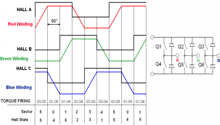 |
Six Step
The six-step waveform control was historically
the first method for controlling brushless machines, because
it was simple and was easy to impliment using discreet logic
chips. There were no MCUs available at that time. This method
is still in common use. |
|
| |
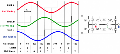 |
Sine Wave
The MCU or digital signal processor made the
sine wave controls feasible. There are a variety of algorithms
available to create sine wave drives using the identical hardware
as the six-step method. This method is most favourable where
the back-emf is also a sine wave. |
|
| |
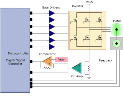
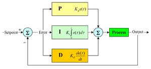
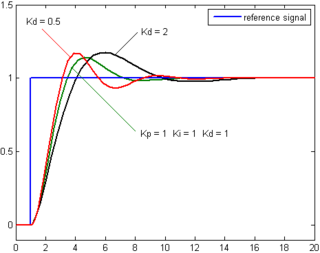
PID
A proportional–integral–derivative
controller (PID
controller) is a generic control loop feedback mechanism
(controller) widely used in industrial control systems – a
PID is the most commonly used feedback controller. A PID
controller calculates an "error" value as the difference
between a measured process variable and a desired setpoint.
The controller attempts to minimize the error by adjusting
the process control inputs. In the absence of knowledge of
the underlying process, PID controllers are the best
controllers. However, for best performance, the PID
parameters used in the calculation must be tuned according to
the nature of the system – while the design is
generic, the parameters depend on the specific system. |
|
|
| |
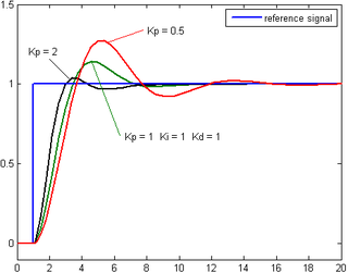
Proportional Term
The proportional term (sometimes called gain) makes a
change to the output that is proportional to the current
error value. The proportional response can be adjusted
by multiplying the error by a constant Kp, called the
proportional gain.
A high proportional gain results in a large change in the
output for a given change in the error. If the
proportional gain is too high, the system can become unstable
(see the section on loop tuning). In contrast, a
small gain results in a small output response to a large input
error, and a less responsive (or sensitive) controller.
If the proportional gain is too low, the control action may
be too small when responding to system disturbances. |
|
|
| |
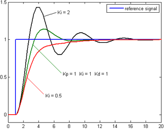
Integral Term
The contribution from the integral term (sometimes
called reset) is proportional to both the magnitude of the
error and the duration of the error. Summing the
instantaneous error over time (integrating the error) gives
the accumulated offset that should have been corrected
previously. The accumulated error is then multiplied by
the integral gain and added to the controller output. The
magnitude of the contribution of the integral term to the
overall control action is determined by the integral gain.
The integral term (when added to the proportional term) accelerates
the movement of the process towards
setpoint and eliminates the residual steady-state error that
occurs with a proportional only controller. However,
since the integral term is responding to accumulated errors
from the past, it can cause the present value to
overshoot the setpoint value (cross over the setpoint and then
create a deviation in the other direction). For
further notes regarding integral gain tuning and controller
stability, see the section on loop tuning. |
|
|
| |
Derivative Term
The rate of change of the process error is calculated by
determining the slope of the error over time (i.e., its first
derivative with respect to time) and multiplying this rate
of change by the derivative gain Kd. The magnitude of
the contribution of the derivative term (sometimes called
rate) to the overall control action is termed the derivative
gain, Kd.
The derivative term slows the rate of change of the controller
output and this effect is most noticeable close to
the controller setpoint. Hence, derivative control is used
to reduce the magnitude of the overshoot produced by
the integral component and improve the combined controller-process
stability. However, differentiation of a
signal amplifies noise and thus this term in the controller
is highly sensitive to noise in the error term, and can
cause a process to become unstable if the noise and the derivative
gain are sufficiently large. Hence an
approximation to a differentiator with a limited bandwidth
is more commonly used. Such a circuit is known as a
Phase-Lead compensator. |
|
|