General
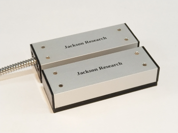
The JR2222 High Security magnetometer features both a legacy interface to existing systems and a RS485 network interface which operates independently. It is designed to operate from the standard 12Vdc security network power lines. The sensor output is open collector for voltage level translation. The output is pulled low in a secure state. An alarm state on the legacy interface occurs by default if power is removed from the device in an active security system.
Each device has a unique serial number stored internally that is displayed on the RS485 network terminal console when powered up, reset or interrogated by a serial number ID command.
The switch and its actuator are matched sets. The actuator on one switch will not function properly on any other switch. Using an actuator on another switch may give the appearance that it is working, however, the operational parameters will be very different and generate diminshed performance and false indications.
Functional Gap
The optimal sensor actuator mounting gap is between 0.10 and 0.20 inches. The minimum sensor actuator mounting gap is 0.0 inches. The device may become
susceptible to defeat, if operated outside recommended parameters, which includes a mounting gap of greater than an optimal upper gap range of 0.20 inches. An alarm will be triggered at 0.25 inches gap, so alignment too close to that zone may trigger false alarms. The size of the gap and actuator alignment can be determined remotely over the RS485 network console from the command set, which is a very useful feature during installation and standard maintenance.
Mounting Surface
The device must be mounted at least 1/4 inch from any ferrous surface. Special spacers are supplied for this purpose which also includes the anti-tamper feature: the switch will not work without it.
Extraneous Field Susceptibility
The device is insensitive to high frequency magnetic fields such as those generated by transformers and electric motors. Low frequency magnetic fields, such as those generated by permanent magnets in the vicinity of the device are interpreted as an attempt to breach the security system and generate an alarm state. All inputs and outputs have Class A EMI suppression filters which also provided a measure of protection against lightning. This intelligent device can detect extraneous magnetic fields introduced to mimic the actuator including but not limited to sliding permanent magnets into an existing gap in an actuated state. |
RS485 Network
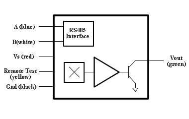
A two wire RS485 interface is integrated into the sensor. The built in command set can be accessed through any serial terminal console, such as Hyperterm, Putty, Tera Term, CuteCom and Hercules. The legacy open collector output operates independently of the RS485 network. When an alarm event starts, both the open collector output and an automatic alert over the network line are initiated. The alarm status and operational parameters of the switch can be determined at any time by commands over the network.
The transceiver rate is 57600 Baud, parity none, handshake off and free mode.
Remote Test
Remote test is automatically conducted when power is applied to the device and may be conducted at any time by placing a 12V pulse on the remote test line. A 12V pulse on the Remote Test line (yellow) resets the device, sets a “Secure State” for 500 ms, sets an “Alarm State” for 500 ms and then returns to active sensing. This feature resets all switches on the same network line at the same time. This is achieved from the hub command console.
Remote test can also be initiated over the RS485 network using the software remote test command (RT) which only resets the individual switch by its unique network ID number. This is achieved from the RS485 network command console, which is separate from the hub command console. The remote test wire (yellow) does not need to be connected for this feature to work.
Thermometer
The digital thermometer may be accessed through the RS485 network using a sensor query command. Temperature units are in degrees Centigrade. A temperature above 55°C or below -10°C will signal an alarm.
The switch will operate up to the absolute temperature limits, but an alarm state will persist when operated outside the secure operating range which means a full status report, AxxxI3, must be used to determine the device status.
False Alarm Immunity
Shock, vibration, and induced line voltage transients are the primary cause of false alarm indication associated with magnetic contacts. There are no electrical contacts to fail. EMI filters eliminate false logic states under normal operating conditions. Consequently, these environmental false alarms have been eliminated.
|
RS485 Network Commands
| Commands Summary |
Prefix |
Command |
Function |
Axxx |
AL |
Switch / Actuator alignment |
GP |
Switch Actuator air gap (inches) |
I0 |
Alarm Status |
I1 |
Temperature °C |
I2 |
Full Status Report |
I3 |
Device identification, version and serial number |
OK |
Is switch present |
RT |
Remote Test |
SAxxx |
Change Network ID number |
SN |
Serial number |
Axxx identifies the switch on the network and the 'xxx' can be any number between 0 and 255 inclusively, for instance: A125. Numbers must be entered with three digits, such as A003 or A075 or A218. No two switches can have the same number on the network or a collision will result. All switches from the factory are preset to 255 and must be set to a unique ID number on the network.
Switch alignment (AL) is useful during installation and normally should be between 1.05 and 0.95. Switch air gap (GP) is also useful during installation to see, remotely, if the switch / actuator gap is within specification. Both number can be useful during normal maintanence to see, from the serial console, if the door has sagged or shows signs of tampering.
The internal temperature sensor is used to thermally linearize the unit over the operating temperature range. The upper limit can also be an indication of fire in the vicinity.
The 'OK' command is used to see if a device is present at the assigned address in heavy network traffic.
Remote test (RT) resets the device at the assigned address only, unlike the network remote test which resets all devices on the network. The entire network remote test can only be initiated from the network hub terminal console, which is separate from the RS485 network command terminal console.
The network ID number (SAxxx), where 'xxx' must be between 0 and 255 inclusively, must be unique on the network and can be changed at any time to another unassigned number. If two devices have the same ID number, one of them must be reset to a different number at the point of installation.
The unique serial number (SN) should be matched in records to the network ID number which would indicate tampering, if different.
All of the commands are intended to be short and explicit to facilitate high speed network traffic and maintain a stable environment during network attacks and any physical attempted breach. For this purpose Real Time Operating Systems are recommended in text mode. A graphics interface takes up most of the system resources and slows everything down to a crawl. Linux is ideal for this kind of network system.
Microsoft Windows is a high security risk, very slow and definitely not suitable for this kind of security system. We absolutely strongly recommend against its use in a high security environment. It is public knowledge that there are many "back doors" in Windows that compromise the integrity of any security system. This also includes Solaris and Apple operating systems. |